
I haven’t looked at this website in years, and I realized recently that it leans very heavily on design (mostly from grad school) with very little analysis. Design is fun and gratifying, but most of the time that I’ve spent doing engineering as a job has focused more on analysis and testing. So, to add a bit of balance I’m documenting a project with more “traditional” engineering - a reaction wheel pendulum.
Reaction wheels are not particularly common in everyday life, but they’re frequently used in satellites for attitude control. I’ve never designed one professionally, and I thought it sounded like a fun personal project that combines a small amount of mechanical design with a bigger focus on electronics and control. The basic premise is simple - attach a motor and a reaction wheel to the end of a pendulum, and use the reaction wheel to swing the pendulum from the bottom (perigee) to the top (apogee), and then use the reaction wheel to sustain balance at apogee.
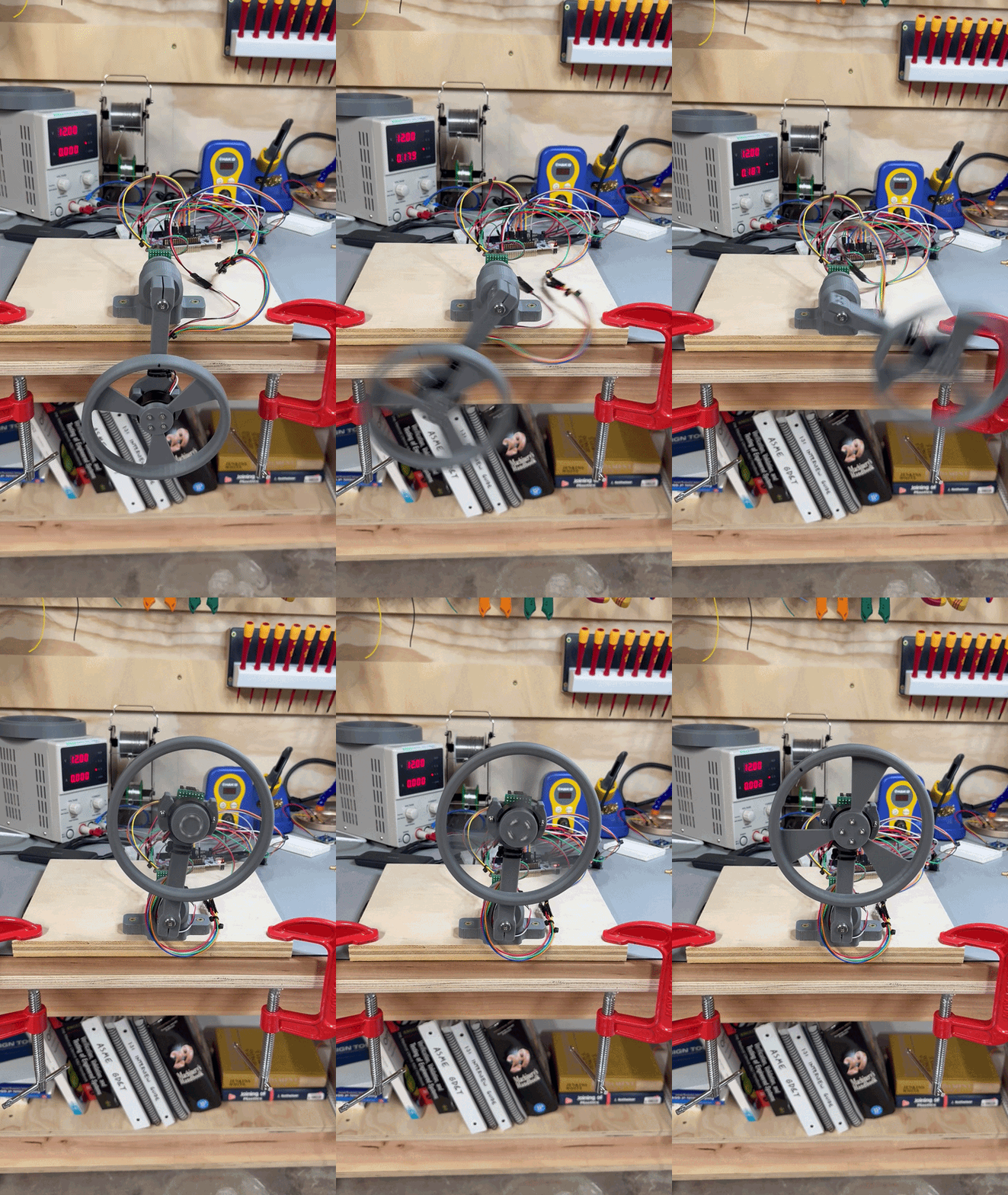
Here is the completed system in action (sketchy wiring included!):
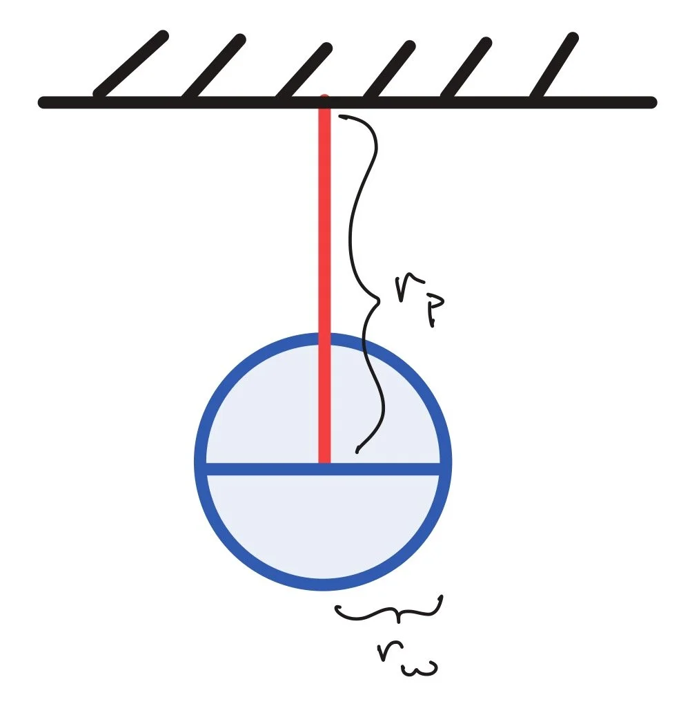
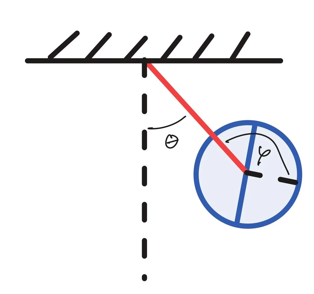
The left image below shows the free body diagram for just the reaction wheel, and the right image below shows the system of pendulum + motor + reaction wheel.
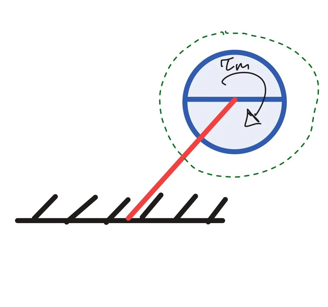
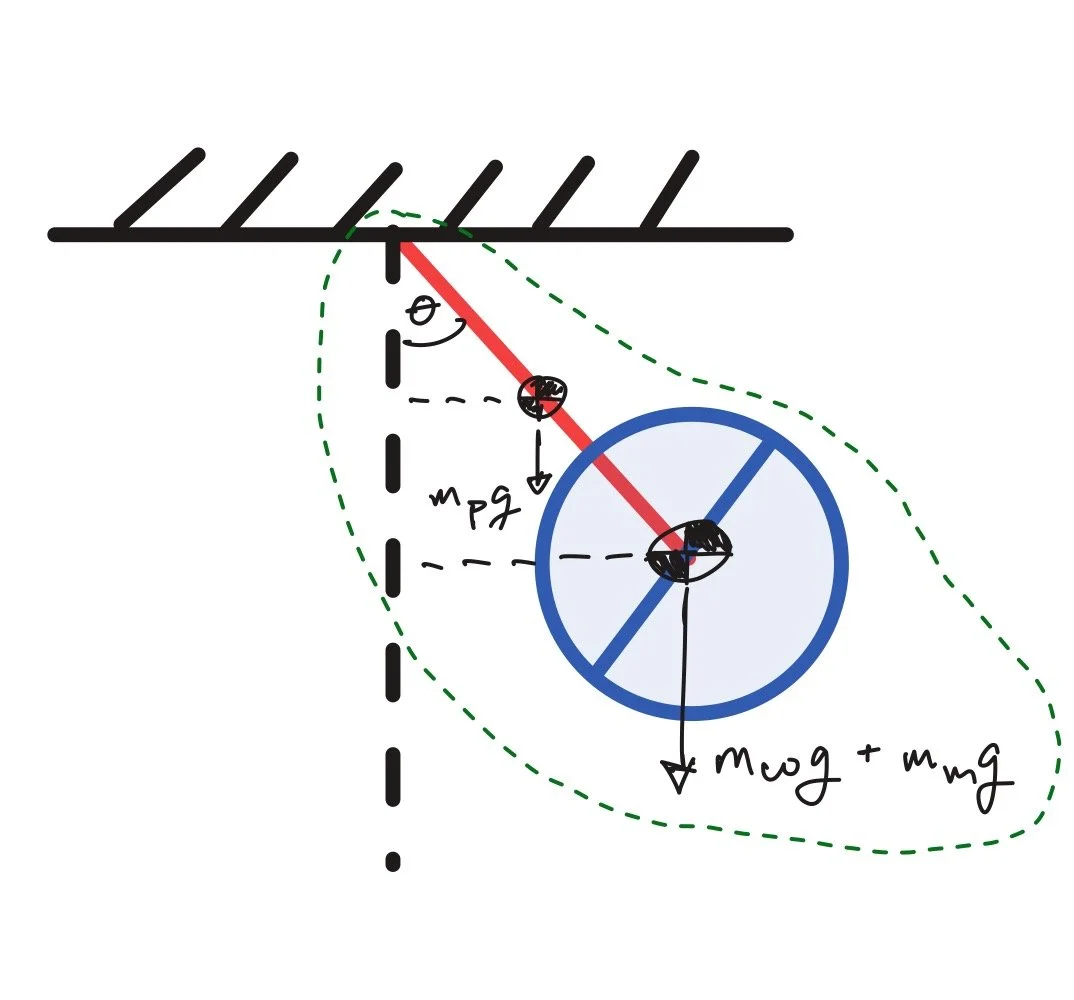
Let’s define some variables:
\(m_p\) : mass of pendulum link
\(m_m\) : mass of motor
\(m_w\) : mass of reaction wheel
\(r_p\) : pendulum length from main pivot to reaction wheel center
\(r_w\) : radius of reaction wheel
\(\theta\) : angular displacement between pendulum and vertical axis
\(\varphi\) : angular displacement between reaction wheel and pendulum
\(J_p\) : mass moment of inertia of everything moving around main pivot
\(J_w\) : mass moment of inertia of reaction wheel relative to wheel center
\(\tau_m\) : motor torque
Newton’s 2nd law in the context of rotation is: \(\sum M = \dot L\), where \(L\) is angular momentum. The more common form is \(\sum M = J\alpha\), but that’s not technically accurate here since it assumes that everything rotating is a single rigid frame, and we have two bodies rotating.
If we just look at the reaction wheel itself, Newton’s 2nd law looks like this:
\(\tau_m = J_w \alpha_{wheel,absolute}\)
In order to correctly capture the angular acceleration of the wheel, we need to incorporate both the acceleration of the wheel relative to the pendulum \((\ddot{\varphi})\) and the center of the wheel relative to the fixed support \((\ddot{\theta})\). This gives us the equation:
\((1)\qquad \tau_m = J_w(\ddot{\varphi} + \ddot{\theta})\)
If we step back to look at the system overall (pendulum, motor, reaction wheel), the only external force acting on it is gravity - everything associated with the motor is internal. This gives us:
\(\sum M = \sum m_i g \ell_i \sin(\theta)\)
Where \(m_i\) and \(\ell_i\) are respective masses and distances to center of mass for individual components. We also know definitionally that:
\(L_{\text{sys}} = \underbrace{J_p\dot\theta}_{\text{everything swinging about the pivot}} + \underbrace{J_w\dot\varphi}_{\text{extra spin the wheel has relative to the body}}\)
Putting these together gives us:
\((2)\qquad \sum M = \dot L_{\text{sys}} = J_p\ddot\theta + J_w\ddot\varphi = \sum m_i g \ell_i \sin(\theta)\)
We can rearrange equation \((1)\) to show that:
\(J_w\ddot{\varphi} = \tau_m -J_w\ddot{\theta}\)
Combining this with equation \((2)\) yields:
\(J_p\ddot\theta + \tau_m -J_w\ddot{\theta} = \sum m_i g \ell_i \sin(\theta)\)
If we set \(\ddot\theta = 0\), that gives us the maximum angle that the pendulum can recover from as it starts to tip:
\(\tau_m= \sum m_i g \ell_i \sin(\theta)\)
\(\theta = \arcsin(\dfrac{\tau_m}{\sum m_i g \ell_i})\)
The sharp-eyed reader will notice that setting \(\ddot\theta = 0\) is pretty suspect here if the pendulum is anywhere but at the apogee or the perigee, but it’s a useful first pass approximation for sizing the pendulum and the wheel.
MECHANICAL DESIGN
The requirements here are pretty straightforward. We want:
low friction at the revolute joints
decent stiffness in structural members, including the base mount
magnets mounted close enough to sensors for reliable measurements (0.5-3mm)
enough cable length so that the pendulum doesn’t actively disconnect as it moves through the full range of motion
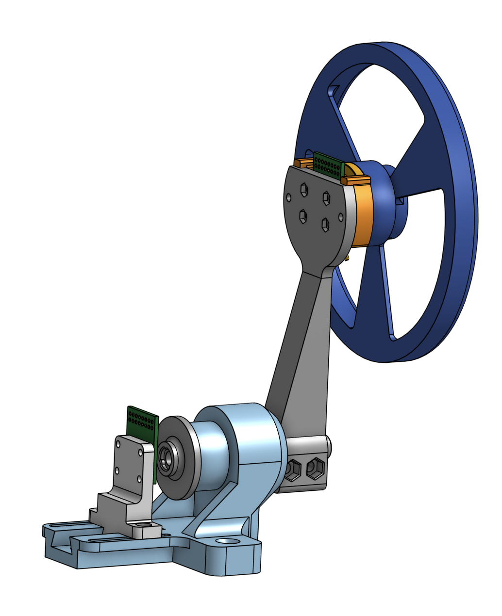
Here is a view of the whole assembly (minus fasteners):
And here is a section view:
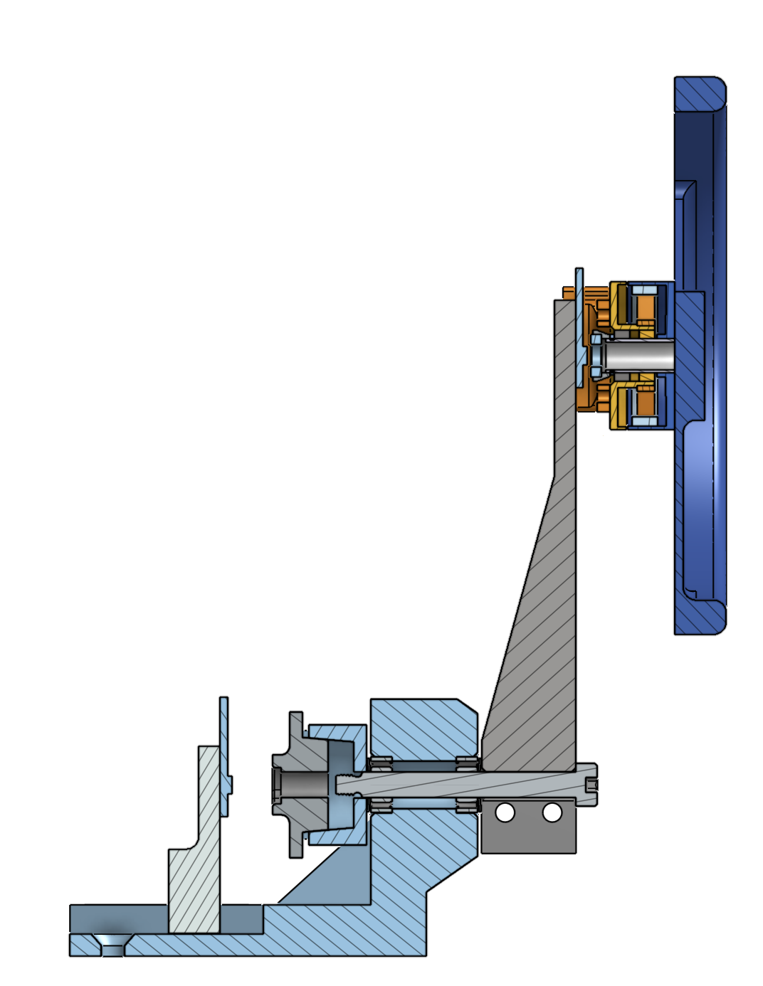
There are two small bearings pressed into the main housing, and a shoulder screw goes through the pendulum and into both bearings. There are belleville washers adjacent to the exterior face of each bearing (>< style) to allow for easy preloading using the threads of the shoulder screw. The threads of the shoulder screw go into a printed receiving cup with a slight taper. This cup has room for a nut (and a socket to install it!), and the 5 degree taper is an easy locking feature so that the magnet can be pressed into a separate component (shown in grey, center of the image) and then pressed into the cup. The press fit allows for easy centering and decent retention, and the cup has notches cut into it so that the flat of a screwdriver can easily pry the magnet holder (male part of the taper) out of it. The position sensor for the pendulum is mounted as a dovetail slide to dial in the appropriate amount of distance between the magnet and the sensor.